

close
Choose Your Site
Global
Social Media
Views: 0 Author: Site Editor Publish Time: 2026-08-06 Origin: Site


Structural longevity depends directly on accurately accommodating building movement across all structural planes. When you specify undersized or oversized gaps, you risk catastrophic material failure. Water ingress and compromised structural integrity often follow these specification errors. Specifiers frequently struggle to align architectural design with structural reality on the job site. The theoretical joint opening dimensions rarely match the physical realities of thermal expansion, seismic activity, and wind sway. Selecting the correct joint requires a rigorous evaluation framework from the very beginning of the design phase. You must calculate the precise nominal gap width, movement capacity, and joint depth before evaluating specific material profiles. This guide provides the technical foundation needed to match physical opening dimensions with the correct structural solutions, ensuring your building envelope remains secure and functional under dynamic loads.
Nominal Width vs. Movement Capacity: The baseline opening dimension is only the starting point; the selected joint must accommodate the maximum calculated expansion and contraction (often expressed as a +/- percentage).
Depth Dictates System Type: Joint depth and substrate composition directly restrict whether a surface-mounted or blockout-mounted system can be utilized.
Exterior vs. Interior Demands: An exterior wall movement joint system requires fundamentally different dimensional tolerances for weather seals and moisture barriers compared to interior flush joints.
As-Built Realities: Always account for construction tolerances; the physical opening on-site frequently deviates from the architectural drawings, requiring adjustable or oversized joint solutions.
Cladding Scale and Spacing: The dimension of exterior cladding components (such as large-format precast or stone panels) directly influences the frequency and calculated width of the wall deformation joint.
Establishing the baseline gap begins at a median temperature. You measure the distance between two structural elements when they are at rest. Architectural aesthetic requirements often push for narrower gaps to maintain clean sightlines. However, structural engineering mandates dictate the minimum safe distance required to prevent collisions. A Wall Deformation Joint must bridge this gap without restricting natural building sway. You must prioritize the structural mandate over visual preferences to prevent concrete spalling and frame buckling. When measuring on site, always take readings at multiple elevations. Concrete forms shift during pours, meaning a gap designed at two inches might measure one and a half inches at the floor slab and two and a quarter inches near the ceiling. Documenting these variations ensures you select a system capable of handling the tightest pinch point.
Field measurements require precision tools and a clear understanding of ambient conditions. If you measure a gap during a freezing winter morning, the building components have contracted. The gap is at its widest. Conversely, measuring during a summer afternoon means the materials have expanded, presenting the narrowest gap. You must adjust your baseline nominal width calculations based on the temperature at the time of measurement. Failing to account for installation temperature leads to systems that either fall out during winter or crush themselves during summer.
You must calculate thermal expansion, seismic drift, and wind load deflection accurately. Engineers use formulaic approaches to determine the change in temperature across the building envelope. These calculations dictate the necessary opening dimension. They show the gap size at maximum compression and maximum expansion. If a joint closes completely during summer expansion, the surrounding masonry will crack under the immense pressure. If it opens too wide during winter, the internal weather seal may rupture, allowing moisture to penetrate the wall cavity.
Wind load deflection plays a massive role in high-rise structures. As wind hits the broad side of a building, the structure bends slightly. This bending creates shear forces across the vertical joints. You must calculate the inter-story drift to understand how much the gap will shift out of plane. Seismic drift adds another layer of complexity. During an earthquake, building wings move independently. The joint must accommodate multi-directional movement—opening, closing, sliding vertically, and shifting horizontally—all without detaching from the substrate.
Large-format facade panels reduce the number of intermediate grout lines across the building exterior. Precast concrete, metal composite, and masonry units concentrate movement forces at the primary structural gaps. This design choice directly impacts the nominal opening dimension. You must adjust the primary joint width to handle the accumulated thermal expansion of these larger finish modules. Fewer joints mean each individual gap must accommodate significantly more movement.
Consider a facade clad in large granite panels versus one clad in standard brick. The brick facade has thousands of mortar joints that absorb micro-movements. The granite facade relies entirely on the engineered expansion gaps. You must calculate the thermal coefficient of the specific cladding material. Darker panels absorb more solar radiation, expanding more than lighter panels. This increased expansion requires a wider nominal gap to prevent the panels from grinding against the joint frame.
The thickness of the wall assembly impacts the available depth for joint anchoring. Concrete masonry units, drywall, and precast concrete offer different anchoring environments. Blockout dimensions require deep recesses cast into the concrete during the initial pour. Surface-mounted applications sit directly on the finished face, requiring less invasive preparation. If your wall assembly lacks sufficient depth, you cannot use heavy-duty blockout frames. You must adapt the specification to fit the physical constraints of the substrate.
Substrate integrity dictates fastener selection and spacing. Hollow concrete block requires different anchors than solid poured concrete or steel studs. You must verify the edge distance—the space between the edge of the gap and the anchor hole. If the edge distance is too small, the concrete will spall when you torque the anchor. This failure compromises the entire installation. Always verify the compressive strength of the substrate before finalizing the anchor schedule.
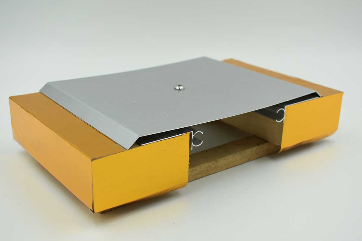
Elastomeric seals handle narrower opening dimensions exceptionally well. They compress and stretch without losing their structural shape or weatherproofing capabilities. Interior applications benefit greatly from flush-mounted systems. They provide minimal visual disruption in high-end spaces like hospital corridors and corporate lobbies. You can achieve a minimalist design by specifying a Rubber Inserted Flush Wall Joint. Color-matching elastomer inserts visually blend into adjacent wall finishes. This approach satisfies both the architect and the structural engineer.
Installation of these flush systems requires precise drywall or plaster finishing. The aluminum retainer frames must sit perfectly level with the final wall surface. Installers mud and tape right up to the edge of the frame. If the framing is out of plumb, the rubber insert will look wavy and unprofessional. You must coordinate closely with the drywall contractors to ensure the rough opening allows for the correct frame depth.
Wide opening dimensions require robust metal systems. Seismic zones demand structural integrity that rubber alone cannot provide. Slide-plate and pan-type aluminum systems bridge large structural gaps safely. They allow multi-directional movement without buckling under pressure. A recessed Aluminum Alloy Wall Expansion Joint allows wall plaster or stone veneer to cover the metal flanges. This minimizes the visible profile while maintaining full movement parameters.
Heavy-duty aluminum systems often incorporate centering bars. These spring-loaded mechanisms keep the cover plate centered over the gap during seismic events. Without centering bars, the cover plate could slide entirely to one side, exposing the gap and creating a hazard. You must ensure the wall cavity is deep enough to house the centering bar hardware. Shallow cavities will restrict the movement of the bar, causing the system to bind and fail.
Exterior opening dimensions must accommodate complex moisture management systems. You need space for secondary moisture barriers, vapor retarders, and primary weather seals. An Exterior Wall Movement Joint System requires specific dimensional tolerances. The joint cavity must integrate proper drainage and weep holes. If the opening is too narrow, you cannot install these critical waterproofing components effectively.
Water management is the most critical aspect of exterior joint design. The primary seal deflects bulk water, but wind-driven rain will eventually bypass it. You must install a secondary moisture barrier behind the primary seal. This barrier catches any infiltrating water and directs it down to weep holes at the base of the wall. The gap must be wide enough for installers to properly seal the edges of the moisture barrier to the substrate. If they cannot reach inside the gap to apply sealant, the system will leak.
Gap Size Range | Recommended System Type | Primary Application | Movement Capacity Focus |
|---|---|---|---|
1" to 4" | Rubber Inserted Flush Joint | Interior Walls, Corridors | Thermal Expansion |
4" to 8" | Aluminum Slide-Plate | Exterior Facades, Seismic | Multi-directional Drift |
8" to 12"+ | Heavy-Duty Pan Type System | Base Isolation Structures | Extreme Seismic Events |
2" to 6" | Surface Mounted Metal Cover | Retrofit Applications | Shear and Settlement |
Evaluating manufacturer specifications requires understanding the movement percentage. A 2-inch joint rated for +/- 50% movement behaves differently than one rated for +/- 100%. Specifying a system based solely on the nominal opening leads to failure. You must verify the movement percentage against the structural engineer's calculations. If the gap is 2 inches and expected movement is 1.5 inches, a 50% system will fail during maximum expansion.
Let us break down the math. A 4-inch gap with a +/- 50% rating can close to 2 inches and open to 6 inches. If your seismic calculations show the gap will open to 7 inches during an event, the 50% system will tear out of the wall. You would need a system rated for at least +/- 75% or a larger nominal gap. Always run the maximum expansion and compression numbers before approving a submittal.
Vertical surfaces in high-traffic corridors face significant abuse. Carts, equipment, and pedestrian traffic impact wall joints daily. You must assess the need for impact-resistant covers. Cover thickness directly impacts the overall joint profile dimension. Thicker covers require deeper wall recesses to remain flush with the surrounding finish. Plan for this depth during the initial framing stage.
In industrial facilities or hospitals, motorized equipment frequently strikes the lower half of the walls. Standard aluminum covers will dent and deform under these impacts. You must specify heavy-duty covers with reinforced backing plates for the bottom four feet of the wall. This modification changes the required blockout depth. You must communicate these varying depth requirements to the concrete and framing crews early in the project.
Intumescent fire blankets alter the required depth and width of the wall opening. Acoustic mass-loaded vinyl also requires dedicated space. You face spatial trade-offs when stacking fire barriers behind the primary joint cover. The opening must be wide enough to allow the fire blanket to fold and compress. If the cavity is too tight, the fire barrier restricts the joint's dynamic movement.
Fire barriers require precise installation to maintain the wall's hourly rating. The barrier must overlap the substrate by a specific margin and be secured with approved fire-caulk and fasteners. If the rough opening is too narrow, installers cannot physically fit their tools inside to secure the barrier. This leads to sloppy installations that will fail a fire marshal's inspection. Always verify the required installation clearances for the specific fire blanket model you specify.
Advanced manufacturer documentation prevents on-site installation errors. You should use detailed CAD sections and BIM models to cross-reference theoretical calculations. Testing certificates verify performance claims. Compare these digital models with real-world physical clearances. This auditing process ensures the specified joint actually fits within the framed wall opening.
Request physical material samples and full CAD details from the manufacturer.
Overlay the joint CAD files onto the architectural wall section drawings.
Verify the blockout depth and width against the structural framing plans.
Confirm the fire barrier and moisture barrier fit within the remaining cavity space.
Review the anchor spacing requirements against the substrate material properties.
Designing wall openings that align with standard, off-the-shelf joint dimensions saves significant time. Standard extrusions fit predictable gaps and depths. When architectural designs force unusual opening dimensions, you must specify custom-machined profiles. Custom fabrication extends lead times and complicates installation. Aligning your structural gaps with standard manufacturer dimensions streamlines the entire construction schedule.
Custom profiles also complicate future maintenance. If a standard cover plate gets damaged, you can order a replacement and install it in days. If a custom profile gets damaged, you must wait weeks for a new extrusion run. You should push back on architectural designs that require custom joints unless absolutely necessary for the building's function. Standardizing gap sizes across the project reduces errors and lowers material costs.
Specifying highly durable, appropriately sized systems prevents water damage. It also eliminates the need for premature structural repairs. Value-engineering the joint size often leads to undersized systems that fail under stress. Investing in robust materials upfront reduces long-term maintenance cycles. A properly sized joint protects the building envelope and extends the lifespan of the interior finishes.
Consider the cost of replacing a failed exterior joint on the tenth floor of a building. You have to rent scaffolding, remove the exterior cladding, extract the failed joint, repair any water damage to the substrate, install the new joint, and replace the cladding. The labor and equipment costs far exceed the initial savings of specifying a cheaper, undersized joint. Do not compromise on movement capacity or weatherproofing to save a few dollars on the initial bid.
Concrete shrinkage and framing errors are common on job sites. These issues result in joint openings that are too wide or too narrow. You must address this risk proactively. Specify systems with high dimensional tolerance. Adjustable anchoring frames allow installers to compensate for uneven substrates. This flexibility prevents project delays when the physical gap deviates from the architectural drawings.
When a gap is cast too wide, you cannot simply fill the extra space with grout. Grout will crack and fall out during movement. You must use transition plates or oversized cover assemblies to bridge the extra distance safely. If the gap is cast too narrow, you may have to grind the concrete back to achieve the minimum required width. Grinding is labor-intensive and generates hazardous silica dust. Accurate formwork is critical.
Opening edges must be perfectly plumb. If they are not, you risk spalling or anchor failure. Mechanical fasteners require a minimum edge distance to hold securely in concrete. If the gap is cast too wide, the edge distance shrinks. Installers cannot safely anchor the joint frame. Proper substrate preparation ensures the anchors engage solid material, maintaining the system's structural integrity.
Before installing any frames, the crew must inspect the substrate. They must remove any loose concrete, form release agents, or debris. The surface must be flat and level. If the concrete is spalled, they must patch it with a high-strength epoxy repair mortar before drilling anchor holes. Installing a joint over compromised concrete guarantees the anchors will pull out during the first major thermal cycle.
Improper sealant application guarantees water ingress. The opening dimension must allow for a proper width-to-depth sealant ratio. If the gap is too narrow, the sealant cannot stretch. If it is too deep without backer rod support, the sealant tears under its own weight. You must ensure the physical opening provides enough space for installers to tool the sealant correctly.
The interface between the joint frame and the wall substrate is the most common point of water entry. Installers must apply a continuous bead of sealant along this edge. They must tool the sealant to ensure full adhesion to both surfaces. If the blockout is too shallow, the sealant bead will be too thin and will rupture. You must verify the blockout dimensions allow for a robust sealant joint.
The successful specification of a wall deformation joint depends entirely on a holistic understanding of the opening dimensions. You must account for gap width, depth, and dynamic movement simultaneously. Ignoring any of these factors leads to system failure, water damage, and costly repairs.
Verify the as-built gap and depth on site before ordering any materials.
Calculate the maximum dynamic movement required by the structural engineer.
Determine the environmental exposure, noting whether the application is interior or exterior.
Select the appropriate material based on these physical constraints and movement requirements.
Request physical submittals and CAD details from joint manufacturers to cross-reference with framing plans.
A: You measure the gap width at a specific ambient temperature. Ensure measurements are taken at multiple points along the vertical plane. This accounts for non-parallel substrates and construction inconsistencies. Record the narrowest and widest points to determine the true as-built dimension.
A: There is no universal standard gap size. Sizes typically range from 2 inches to over 12 inches. The required width depends heavily on the building's height, overall footprint, and local seismic requirements.
A: Yes. Aluminum systems utilize slide-plate designs or centering bars. These components are specifically engineered to accommodate multi-directional seismic drift safely within large wall openings.
A: These joints are best suited for interior applications with smaller opening dimensions, typically 1 to 4 inches. They provide a smooth, hygienic, and aesthetically unobtrusive finish suitable for hospitals and commercial corridors.
A: Shallow depths restrict the use of blockout-mounted systems and heavy-duty fire barriers. This physical limitation forces the use of surface-mounted frames, which may protrude slightly from the finished wall surface.
A: The joint cover risks falling into the gap or failing under maximum expansion. You must transition to a larger joint profile or utilize custom transition plates to bridge the unexpected distance safely.


