

close
Choose Your Site
Global
Social Media
Views: 0 Author: Site Editor Publish Time: 2026-08-08 Origin: Site


Industrial floor joints frequently fail because specifiers rely on gap width and general building load ratings while ignoring localized load dynamics. When a forklift carrying a massive payload rolls across a gap, the concentrated pressure exerts tremendous force on the joint edges. If the system is not engineered for that specific point load, the surrounding concrete fractures. The joint cover bends. The entire assembly fails.
Inadequate load data collection leads directly to joint deflection, severe concrete spalling, and premature failure of material handling equipment (MHE). A broken joint acts as a speed bump, destroying forklift tires and disrupting automated guided vehicles. This causes costly facility downtime. Selecting a resilient Heavy Duty Floor Expansion Joint requires precise calculations of static, dynamic, point, and live loads. You must understand the framework for gathering this data to evaluate and specify the correct joint profile.
Total floor load capacity (PSF) is insufficient for joint specification; localized point load and wheel contact area are the critical metrics.
Dynamic impact factors—such as forklift speed, braking, and turning forces—must be calculated alongside static weight using benchmark multipliers.
Matching the joint material (e.g., metal vs. elastomeric) to the specific tire type (solid polyurethane vs. pneumatic) prevents premature wear.
Adherence to ACI 302 concrete compressive strength baselines is required to ensure the substrate can support the specified joint under heavy loads.
Zonal variations across a facility dictate different joint load ratings, requiring tailored specifications for loading docks, high-bay aisles, and structural slabs-on-grade.
A successful joint installation maintains zero deflection under maximum load. It provides a seamless transition for wheeled traffic and prevents edge spalling over its lifespan. When specifications fall short, the physical consequences accumulate rapidly across the facility floor.
Unsupported loads at the joint gap cause the surrounding concrete to fracture. When a hard wheel strikes an uneven or deflecting joint cover, the impact transfers directly to the concrete edge. Over time, this repetitive striking breaks the concrete matrix. This leads to severe spalling. The widening crater exposes the joint system further, accelerating the degradation of both the floor and the joint assembly. You will see the aggregate exposed and the metal retainers bending under the continuous assault of warehouse traffic.
Joints placed on grade face different mechanical stresses than those on structural suspended slabs. Slabs-on-grade rely on the subgrade for continuous support. Load transfer is relatively direct into the earth below. Suspended slabs are subjected to bending and deflection under heavy loads. A joint on a suspended slab must accommodate these vertical deflections without compromising its load-bearing integrity. It cannot tear away from its embedment when the slab flexes under the weight of a loaded pallet jack.
Joint failure compounds financial losses through equipment damage. Damaged forklift wheels require frequent replacement. The jarring impacts damage sensitive payloads. For facilities utilizing automated guided vehicles (AGVs), a compromised joint disrupts navigation sensors. This causes the equipment to halt or misroute. The resulting operational downtime halts production lines and shipping schedules.
Equipment Type | Impact of Joint Failure | Operational Consequence |
|---|---|---|
Counterbalance Forklifts | Shredded polyurethane tires, damaged suspension | Frequent maintenance cycles, dropped payloads |
Automated Guided Vehicles (AGVs) | Sensor misalignment, laser navigation errors | Route stoppage, manual reset requirements |
Electric Pallet Jacks | Bent load wheels, cracked undercarriages | Operator fatigue, reduced transit speeds |
Reach Trucks | Mast vibration, hydraulic seal wear | Unsafe high-bay lifting, fluid leaks |
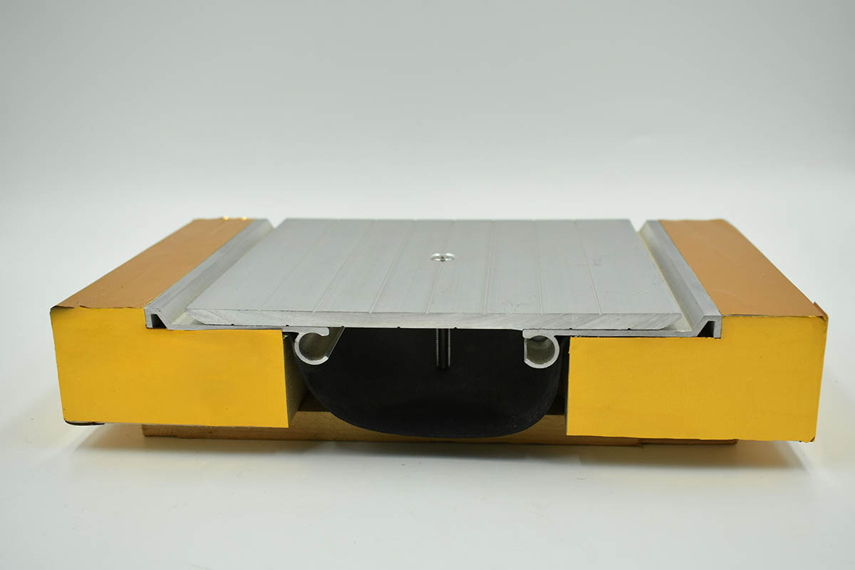
General building load ratings provide a false sense of security. Accurate specification demands granular data regarding how weight interacts with the floor surface at the exact location of the gap.
Static load refers to stationary heavy machinery or racking systems resting on the floor. Dynamic load accounts for moving traffic, which exerts significantly higher forces. Calculating the multiplier effect of dynamic loads is mandatory. Acceleration, braking, and turning add impact factors that multiply the static weight of the vehicle and its payload. Live load calculations apply benchmark factors to ensure the joint can withstand sustained operational stress.
Determine the maximum static weight of the heaviest vehicle fully loaded.
Identify the maximum speed of the vehicle in the specific operating zone.
Apply a dynamic multiplier (often 1.5x to 2.0x) to account for braking and acceleration forces.
Factor in a 1.25 multiplier for continuous 7-day loading cycles if the facility operates around the clock.
Calculate the lateral shear force if the traffic approaches the joint at a skewed angle.
Overall floor load capacity, typically expressed in pounds per square foot (psf) or kilograms per square meter (kg/m²), is irrelevant for joint selection. A 500 psf floor rating does not mean the floor can handle a 10,000-pound forklift concentrated on four small wheels. You must calculate the exact weight distributed over the specific square inch or centimeter of a wheel's contact patch. This load contact area determines the actual pressure exerted on the joint cover.
The type of tire rolling over the joint drastically alters the load transfer dynamics. Hard polyurethane wheels have a very small contact area. This results in high-impact, concentrated point loads that test the shear strength of the joint. Pneumatic tires cushion the impact and spread the weight over a larger contact area. This reduces the localized stress on the joint assembly.
Tire Material | Contact Area Profile | Load Transfer Characteristic | Joint Stress Level |
|---|---|---|---|
Solid Polyurethane | Extremely Small (1-3 sq inches) | Rigid, zero shock absorption | Severe Point Load / High Shear |
Solid Rubber | Small to Medium (3-6 sq inches) | Moderate dampening | High Point Load |
Pneumatic (Air-filled) | Large (10+ sq inches) | High shock absorption | Distributed Load / Low Shear |
Measuring the volume of daily passes helps determine the fatigue life required of the joint system. The angle of approach dictates necessary shear strength. Traffic moving perpendicular to the joint stresses the system differently than skewed or turning traffic. Turning traffic applies lateral forces that can rip a poorly anchored joint from its bedding.
Facilities rarely have uniform load requirements. Mapping localized requirements across different zones ensures proper specification. Heavy-impact loading docks require maximum durability. High-frequency main transit aisles need smooth transitions to prevent equipment wear. Static-heavy racking zones require stability under sustained pressure. Each zone demands a specific joint profile tailored to the exact operations occurring in that footprint.
Once the load data is compiled, map it to specific structural solutions. Different joint designs offer varying balances of load capacity and movement accommodation.
For environments with extreme point loads and hard-wheeled traffic, a Metal Lock Floor Joint provides superior durability. The interlocking metal plates distribute weight across the slab. This prevents localized deflection. As a wheel passes over the gap, the load is continuously supported by the metal structure. This protects the concrete edges from impact. The interlocking fingers ensure that there is never a moment where the wheel drops into a void.
Environments requiring vibration dampening and high movement capacity alongside moderate dynamic loads benefit from a Heavy Duty Floor Movement Joint featuring reinforced elastomeric inserts. These systems absorb impact and accommodate thermal expansion well. Specifiers must carefully evaluate the trade-off between load capacity and movement accommodation. Elastomeric seals cannot support the same extreme point loads as solid metal systems. They will compress under the weight of a solid polyurethane wheel carrying a heavy payload.
Facilities subject to seismic activity, heavy settlement, or high thermal variance require specialized solutions. A Ground Deformation Joint is engineered to maintain load-bearing integrity during multi-directional structural shifts. These systems utilize complex sliding mechanisms and robust anchoring. They ensure the floor remains safe for traffic even after significant structural movement. The cover plates slide over each other to accommodate wide variations in gap width while maintaining a flush surface.
Specifying a Load Bearing Floor Expansion Joint requires adherence to established engineering standards. The surrounding substrate must handle the transferred forces.
The joint is only as strong as the concrete holding it. ACI 302 guidelines recommend a minimum compressive strength of 3,500 to 4,000 PSI for warehouse floor slabs. If the concrete lacks sufficient compressive strength, the localized pressure transferred through the joint anchors will cause the substrate to crumble. This leads to system failure regardless of the joint's intrinsic strength. The anchors will simply pull out of the weak concrete matrix.
Industrial design manuals for concrete floor slabs on grade emphasize subgrade modulus requirements. The subgrade must provide uniform support to prevent the slab from deflecting under heavy loads. Deflection unevenly stresses the expansion joint. Proper base preparation is non-negotiable for heavy-duty applications. You must compact the subgrade to the engineer's exact specifications before pouring the slab.
Manufacturer testing data provides insight into safe spans and support spacing. Specifiers must read load data sheets to verify that the tested parameters match their facility's actual conditions. Using span tables and safe area calculators helps estimate the load distribution around the joint. This ensures the structural shear limits are not exceeded. Always verify if the manufacturer's load rating is based on a static uniform load or a dynamic point load.
Even the most robust joint system will fail if installation protocols are ignored. Proper implementation dictates long-term performance on the warehouse floor.
Uneven slab elevations or inadequate block-out preparation create immediate risks. If the joint cover does not sit perfectly flush with the finished floor, wheeled traffic will strike the edge. This causes severe impact damage. Precision leveling during installation is mandatory. The contractor must use self-leveling underlayments or epoxy mortars to ensure the block-out base is perfectly flat and at the correct depth.
High-strength epoxy bedding and proper anchor spacing ensure the joint transfers the load to the slab without shearing. The spacing of structural floor beams and joint supports directly affects localized load-bearing capacity. Insufficient anchoring allows the joint to shift under dynamic loads. This leads to rapid failure. You must follow the manufacturer's exact torque specifications for all concrete anchors.
Specifiers must balance the need for a highly rigid load-bearing system with the necessity of maintaining flexibility for thermal expansion. Overly rigid systems resist movement, causing the concrete to crack elsewhere. Overly flexible systems deflect under heavy point loads. The collected load data dictates the correct balance. You cannot guess these parameters; you must calculate them based on the heaviest equipment operating in the space.
Successful specification of a heavy-duty floor joint relies entirely on granular point-load, contact-area, and localized live-load data. General building load ratings will lead you to specify the wrong system. Ignoring these metrics guarantees premature failure, concrete spalling, and costly repairs.
Consult with a structural engineer to calculate exact dynamic multipliers for your specific material handling equipment.
Request comprehensive point-load testing data from joint manufacturers before finalizing procurement.
Ensure your concrete contractor strictly adheres to ACI 302 compressive strength requirements during the block-out pour.
Audit the installation process to verify that the joint cover sits perfectly flush with the adjacent concrete slab.
A: Floor load capacity (PSF) measures the average weight a floor can support over a large area. Point load measures the concentrated force exerted on a specific, small area, such as the contact patch of a forklift wheel. Expansion joints must be specified based on point load to prevent localized failure.
A: Forklifts exert severe dynamic impacts when braking, accelerating, or turning. Hard polyurethane tires concentrate this weight into a tiny contact area. This creates massive shear forces that bend joint covers and fracture the surrounding concrete if the joint is under-specified.
A: Yes, provided it offers a zero-bump transition and continuous support. AGVs require perfectly smooth floors to protect their sensitive navigation sensors and prevent load shifting. The joint must not deflect under the AGV's weight.
A: ACI 302 standards recommend a minimum compressive strength of 3,500 to 4,000 PSI for warehouse floor slabs. Sufficient compressive strength is required to ensure the concrete can withstand the forces transferred through the joint anchors without spalling.
A: Specify a metal lock joint when the facility utilizes heavy equipment with solid polyurethane wheels, or when point loads exceed the shear capacity of elastomeric materials. Metal systems provide continuous support across the gap, preventing deflection under extreme concentrated weight.
A: The load contact area is calculated by dividing the total weight resting on a specific wheel by the actual footprint (in square inches or centimeters) of that tire where it touches the floor. This reveals the true pressure exerted on the joint.
A: Suspended slabs experience bending moments and vertical deflection under heavy loads, requiring joints that can accommodate these multi-directional shifts without failing. Slabs-on-grade are continuously supported by the subgrade, making direct load transfer the primary concern.


