

close
Choose Your Site
Global
Social Media
Views: 0 Author: Site Editor Publish Time: 2026-08-10 Origin: Site


Industrial flooring failures often start right at the slab edges. When hard-wheeled material handling equipment (MHE) repeatedly strikes these transition zones, concrete and steel separate under high-traffic conditions. This separation causes severe joint edge spalling, leading to operational disruptions and safety hazards. Relying on chemical adhesion or intermittent anchors to secure heavy-duty joint systems to concrete matrices is insufficient. These traditional methods fail to withstand dynamic loading, thermal cycling, and inevitable concrete shrinkage. To solve this, engineers utilize the mechanical advantage of continuous interlocking. Engineered voids within a Punched Steel Armor Joint fundamentally change the structural relationship between the joint profile and the concrete slab. By allowing concrete to flow directly through the steel, these punched holes create a monolithic bond. This integration ensures long-term edge protection, eliminating the micro-movements that lead to catastrophic floor failure.
Punched holes transform surface-level adhesion into a continuous, monolithic mechanical interlock, preventing joint separation during concrete shrinkage.
Unrestricted concrete flow through the punched matrix eliminates subsurface voids and honeycombing, a primary cause of premature edge failure under heavy dynamic loads.
Evaluating a punched and bent armored joint requires analyzing aggregate size compatibility, hole geometry, and concrete slump to ensure proper consolidation.
While cold drawn flat steel armored joints with welded studs offer traditional anchoring, continuous punched profiles distribute stress more evenly and eliminate weld-fatigue risks.
Specifying punched mechanical bonds drastically reduces facility lifecycle costs, maintenance overhead, and operational downtime.
A successful joint installation demands strict structural requirements from the ground up. The system must achieve zero differential deflection across the transition when subjected to heavy axle loads. It requires high resistance to shear stress generated by forklift traffic, pallet jacks, and automated guided vehicles. Most importantly, it needs absolute lateral immobility relative to the concrete slab. If the steel profile shifts even a fraction of a millimeter under load, the surrounding concrete will crack. We measure success by the joint's ability to act as a seamless extension of the concrete itself, transferring loads without independent movement. Achieving this requires a bond that goes beyond surface friction, demanding a physical integration of materials.
Field observations consistently show that joints failing to meet these criteria exhibit early signs of distress within the first six months of facility operation. You will notice fine hairline cracks running parallel to the steel profile. These cracks indicate that the steel has broken its bond with the concrete and is moving independently. Once this micro-movement starts, the deterioration accelerates rapidly. The success criteria therefore hinge on preventing that initial bond failure through superior mechanical design rather than relying on the chemical adhesion of cement paste to smooth steel.
Concrete naturally shrinks away from embedded steel components during the curing process. As moisture leaves the slab through hydration and evaporation, the overall volume decreases. This shrinkage pulls the concrete matrix away from the rigid steel face, creating microscopic gaps along the joint line. While these gaps might be invisible to the naked eye, they represent a complete loss of structural adhesion. When heavy forklift wheels impact the joint, dynamic loading exacerbates these micro-separations. The repeated impact forces the steel to vibrate against the unsupported concrete edge.
This vibration acts like a jackhammer on a microscopic scale. The steel profile, lacking continuous support, flexes slightly with every wheel pass. This flexing pulverizes the adjacent concrete, turning solid matrix into dust. Over time, the micro-gaps widen into visible fissures. The steel lip loses its foundation, leading to macro-level spalling and catastrophic joint failure. Understanding this mechanism is why modern floor design moves away from smooth embedded plates and toward systems that physically lock the concrete and steel together, neutralizing the effects of shrinkage.
Temperature and moisture gradients within the concrete slab cause the edges to curl upward over time. The top of the slab dries faster than the bottom, creating a differential volume change. The upper surface shrinks more than the lower surface, forcing the slab edges to lift off the subbase. A lack of continuous vertical anchorage along the Edge Protection Armor Joint allows the steel profile to delaminate from the concrete face during this curling process. Without a mechanical lock holding the steel firmly to the full depth of the slab edge, the joint becomes exposed.
When a slab curls, the joint edge is left suspended in the air, completely unsupported by the subgrade below. As a forklift drives over this suspended edge, the entire load is transferred to the joint profile and the immediate concrete interface. If the steel is not mechanically locked into the lower half of the slab, the downward force will rip the steel away from the concrete. Continuous vertical anchorage, achieved through engineered voids, ensures the steel moves with the slab during curling, maintaining its protective position without delaminating.
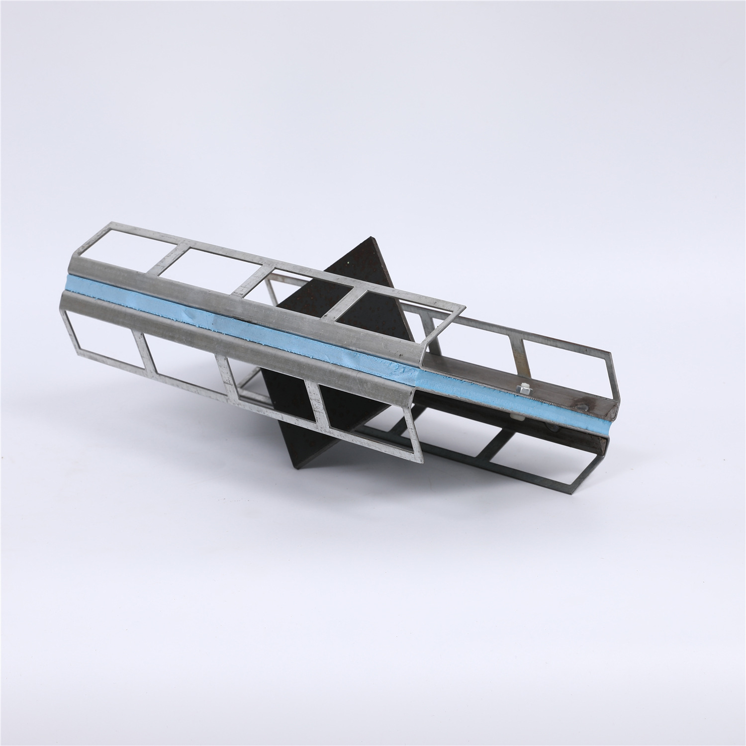
Punched holes allow wet concrete paste and fine aggregates to flow directly through the steel profile during the pour. This creates a continuous "concrete key" that physically locks the plate inside the slab. Instead of relying on the weak chemical bond between smooth steel and curing concrete, the mechanical interlock ensures the steel and concrete act as a single, unified structural element. The concrete cures through the voids, gripping the steel from both sides. This physical barrier prevents the steel from pulling away during the shrinkage phase.
The mechanics here are straightforward but highly effective. Imagine trying to pull a solid sheet of metal out of dried mud versus pulling a piece of chainlink fence out of the same mud. The solid sheet slides out once the surface friction is broken. The fence is locked in place by the mud that has dried through its openings. A punched profile applies this exact principle to industrial flooring. The concrete keys formed through the steel plate possess immense shear strength, making it physically impossible for the joint to separate from the slab without destroying the concrete itself.
A continuous perforated bond line offers significant stress distribution benefits compared to isolated, spaced-out anchor points. Intermittent anchors, such as welded studs spaced every 300mm, concentrate load forces into small, localized tension zones within the surrounding concrete matrix. When a wheel strikes the joint between two studs, the steel flexes, and the stress is transferred entirely to those two specific anchor points. These high-stress points are highly prone to cracking and fatigue failure.
A continuous punched profile distributes the impact energy evenly along the entire length of the joint. Because the concrete key is continuous, every millimeter of the steel profile is supported and anchored. This uniform load transfer minimizes localized stress and preserves the integrity of the concrete edge. The impact of a forklift wheel is absorbed by the entire slab edge rather than being focused on a few vulnerable welds. This continuous support is what allows punched systems to survive in high-traffic environments where intermittent systems fail.
Traditional solid steel plates trap air underneath them during installation. As concrete is poured and vibrated, air bubbles naturally rise to the surface. However, when they encounter the solid horizontal lip of a traditional joint, they cannot escape. This trapped air forms voids directly beneath the critical load-bearing surface of the steel. These voids mean the steel is resting on air rather than solid concrete, creating an immediate weak spot that will collapse under the first heavy load.
A punched profile acts as an integrated venting system. It allows trapped air to escape upward through the holes while the concrete consolidates completely beneath and through the steel edge. As the poker vibrator liquefies the concrete, the air is forced out through the punched voids, and the heavy paste flows in to take its place. This guarantees 100% contact between the steel and the concrete, eliminating the hidden subsurface voids that plague solid plate designs.
The structural geometry of a Punched and Bent Armored Joint offers superior rigidity. The bending process creates a multi-dimensional profile that resists twisting and warping during installation. When concrete is poured against a flat plate, the hydrostatic pressure can cause the plate to bow. Bending the steel adds a geometric stiffness that counteracts this pressure. Integrated continuous rebar or concrete doweling passing directly through the punched holes significantly enhances this 3D rigidity.
This design ensures precise structural alignment throughout the concrete pouring and curing phases. Keeping the joint perfectly flush with the finished floor level is non-negotiable for a successful installation. The bent profile provides a stable platform for screeding equipment, while the punched holes allow the concrete to lock the entire assembly in place before any movement can occur. This combination of geometric stiffness and mechanical interlocking makes punched and bent profiles highly reliable for large-scale industrial pours.
Traditional profiles often utilize a Cold Drawn Flat Steel Armored Joint relying on welded shear studs for bonding. The cold drawing process provides tight steel tolerances, sharp edges, and a smooth finish. This results in a very clean-looking joint line. However, the reliance on welded studs introduces significant structural vulnerabilities. Stud welding introduces heat-affected zones (HAZ) into the steel. These zones alter the local metallurgy of the cold-drawn steel.
The intense heat of welding destroys the work-hardened properties achieved during the cold drawing process. It creates brittle points at the base of every stud. Under repetitive impact loads from hard-wheeled traffic, these brittle zones are susceptible to fatigue cracking. Once a stud snaps, that section of the joint loses its anchorage entirely. While cold-drawn steel offers excellent dimensional accuracy, the necessary welding process compromises the long-term durability of the anchoring system.
Engineers must weigh the structural differences between these two anchoring methods. The choice directly impacts the lifespan of the floor and the maintenance budget of the facility. The table below outlines the primary operational trade-offs between intermittent welded anchors and continuous mechanical interlocking.
Evaluation Metric | Welded Shear Studs | Punched Holes (Mechanical Interlock) |
|---|---|---|
Risk of Weld Fatigue | High (subject to dynamic impact failure at the HAZ) | Zero (no welds required for anchoring to the slab) |
Localized Stress Concentrations | High (stress focused entirely at individual stud locations) | Low (stress distributed continuously along the concrete key) |
Installation Depth Limitations | Requires sufficient slab depth for stud clearance and cover | Highly adaptable to shallow slab profiles and toppings |
Uniform Load Distribution | Poor (intermittent transfer causes micro-flexing) | Excellent (continuous concrete key prevents flexing) |
Venting of Trapped Air | Poor (solid plate traps air beneath the lip) | Excellent (holes act as vents during vibration) |
Edge geometry dictates how wheels interact with the joint. Straight-cut edges expose a linear gap to wheel impacts. When a wheel crosses a straight joint, it drops slightly into the gap and strikes the opposing steel edge, causing jolts and vibration. This impact damages the wheel, the forklift suspension, and eventually the joint itself. Sinusoidal or wave designs eliminate this linear impact. The wheel remains in continuous contact with the floor surface across the wave profile, bridging the gap diagonally.
When combined with a punched hole anchoring system, wave profiles completely eliminate wheel impact jolts while maintaining an unbreakable bond with the concrete slab. The wave geometry ensures smooth load transfer, while the punched holes ensure the complex steel shape remains permanently locked into the concrete matrix. This combination represents the highest tier of joint protection available for ultra-high-traffic facilities.
Structural features dictate physical outcomes on the job site. Hole diameter, oval or circular geometry, and spacing directly influence concrete flow. If the holes are correctly sized relative to the concrete mix, they eliminate honeycombing and air pockets behind the joint. The aggregate interlock achieved through these voids ensures the steel becomes a permanent, immovable fixture within the slab matrix. The paste must flow freely, but the coarse aggregate must also engage with the steel matrix to provide maximum shear strength.
We evaluate the effectiveness of the hole geometry by observing the consolidation during the pour. A properly designed punched profile will show concrete paste extruding through the holes as the vibrator passes by. This visual confirmation guarantees that the void behind the steel is completely filled. If the holes are too small, the aggregate will bridge across the opening, filtering out the coarse material and allowing only weak cement paste to pass through, compromising the mechanical lock.
Durability under high-frequency, heavy-axle loads requires a monolithic bond. The mechanical interlock achieved through punched holes prevents the steel lip from bending. It stops the profile from vibrating loose under the constant pounding of polyurethane forklift wheels. This integration ensures the joint outlasts the surrounding concrete surface. We measure this durability in millions of axle passes.
In facilities operating 24/7, a standard joint might fail within two years. A punched mechanical system, properly installed, will last the lifetime of the slab. The continuous support prevents the steel from fatiguing. Because the steel cannot move independently of the concrete, there is no friction generated between the two materials. This lack of friction means no concrete dust is produced, no micro-cracks form, and the joint remains solid and flush year after year.
Material selection depends entirely on facility exposure and operational environment. Structural carbon steel suits standard dry warehousing where moisture is not a concern. Hot-dip galvanized steel prevents corrosion in damp environments, wash-down areas, or unconditioned spaces. Stainless steel options for punched joints are mandatory for food processing, chemical exposure, and temperature extremes like cold storage facilities. Matching the steel grade to the environment prevents premature degradation of the joint system.
Using standard carbon steel in a wet environment will lead to rust. Rust expands as it forms, creating internal pressure that will spall the concrete away from the joint, regardless of how well it is anchored. Conversely, specifying stainless steel for a dry warehouse is an unnecessary expense. Evaluating the environmental suitability ensures the mechanical bond is not compromised by chemical or oxidative attack over the facility's lifespan.
Modern industrial floors utilize laser-screed, large-bay continuous pours to maximize efficiency and minimize the number of formed joints. Punched joints offer high scalability for these methods. They allow for rapid installation and reliable concrete integration over long runs. The continuous anchoring design ensures the joint remains stable and perfectly aligned even as heavy screeding equipment passes over it during the pour.
In large-bay construction, the joint must act as a rigid formwork edge while also integrating seamlessly into the final slab. The punched profile allows contractors to set hundreds of meters of joint per day. The integrated dowel systems provide load transfer between the massive concrete panels, while the punched holes guarantee the armor remains locked to the edge. This scalability makes them the preferred choice for logistics centers and mega-warehouses.
Aggregate bridging is a critical technical risk during installation. If the aggregates in the concrete mix are too large, they block the punched holes, preventing full paste penetration. Strict guidelines dictate matching the maximum aggregate size (Dmax) to the punched hole diameter. The hole must be significantly larger than the Dmax to ensure unimpeded flow and complete consolidation behind the steel profile. Failure to coordinate the mix design with the joint specification will result in severe honeycombing.
Contractors must review the concrete submittals before ordering the joint systems. If the mix utilizes a 32mm aggregate, a joint with 20mm punched holes will fail to consolidate. The coarse aggregate will jam in the holes, creating a dam that prevents the cement paste from filling the voids beneath the steel lip. We recommend a hole diameter at least 1.5 to 2 times larger than the Dmax to guarantee smooth flow and robust mechanical interlocking.
Proper consolidation requires strict protocols on the floor. Internal vibration using poker vibrators along the joint line is mandatory. This forces the concrete paste and fine aggregates through the punched holes, eliminating entrapped air. The vibrator must be inserted vertically, close to the steel profile, and withdrawn slowly to allow the air bubbles to escape. However, contractors must avoid over-vibration.
Excessive vibration causes segregation of the concrete paste. It drives the heavy coarse aggregates down and away from the joint, leaving only weak, watery cement paste at the critical interface. This weak paste will shrink excessively and lack the compressive strength needed to support the steel edge under load. The vibration protocol must be precise: enough energy to liquefy the mix and force it through the holes, but not so much that the mix segregates.
Installation risks center on joint straightness and elevation. High-tolerance industrial floors must adhere to strict industry standards like TR34 or ACI 302. Fixing pins, adjustment brackets, and installation jigs ensure the joint remains perfectly flush during the pour. Proper leveling prevents the creation of a physical step across the joint, which would immediately subject the steel to damaging impact loads.
Establish the finished floor elevation using a laser level and mark the subgrade.
Drive heavy-duty fixing pins into the subgrade at regular intervals along the joint line.
Mount the joint profile to the pins using precision adjustment brackets.
Use a string line and laser to dial in the exact elevation and straightness, locking the brackets tightly.
Verify the alignment immediately before the concrete pour reaches the joint, as construction traffic can bump the setup.
Even a 2mm height difference across a joint will cause forklift wheels to slam into the exposed steel edge. This impact will eventually destroy any joint, regardless of how well it is anchored. The fixing system must be rigid enough to withstand the pressure of the wet concrete and the vibration process without shifting out of tolerance.
The mechanical interlock provided by a punched steel profile offers superior long-term structural integrity over traditional welded-anchor joints. By allowing concrete to flow through the steel, it eliminates voids, prevents delamination during concrete shrinkage, and distributes dynamic loads evenly across the slab edge. Specify these systems based on facility traffic volume, wheel types, load profiles, and expected floor lifespan. Polyurethane wheels carrying heavy loads require the continuous support that only a punched mechanical bond can provide. When you eliminate the micro-movements at the slab edge, you eliminate the root cause of industrial floor failure.
Review concrete mix designs to ensure the maximum aggregate size is compatible with the joint's punched hole diameter.
Consult with joint manufacturers to specify the correct material finish based on facility environmental conditions.
Implement strict internal vibration protocols during the pour to guarantee full concrete consolidation through the joint profile.
Utilize precision adjustment brackets to maintain strict elevation tolerances in accordance with TR34 or ACI 302 standards.
A: The optimal hole diameter depends entirely on the concrete mix design. It must prevent aggregate bridging. Typically, the hole diameter should be at least 1.5 to 2 times the maximum aggregate size (Dmax) in the concrete mix to ensure unimpeded flow and full consolidation behind the steel profile.
A: Punched and bent profiles are lighter yet offer superior continuous bonding capability. Unlike traditional angle iron, which relies on intermittent welded anchors that can fatigue, the punched design provides a continuous mechanical lock that prevents concrete shrinkage gaps and resists slab curling.
A: Retrofitting these joints is highly complex and generally not recommended. They are primarily specified for new pours. Retrofitting requires extensive slot-cutting, precise leveling, and specialized non-shrink grouts, making it difficult to achieve the monolithic bond required for heavy traffic.
A: A workable slump is essential for flowability without compromising strength. Using superplasticizers helps achieve the necessary flow to penetrate the punched holes. Avoid excessive water-cement ratios, as adding too much water causes localized shrinkage and weakens the concrete edge.
A: Punched holes secure the armor steel to the concrete slab edge to prevent spalling. They do not transfer loads between slabs. A separate dowel plate system, integrated below the armor profile, manages the actual load transfer between the adjacent concrete panels.
A: Voiding is typically caused by poor vibration practices that fail to release trapped air. Other causes include incompatible aggregate-to-hole sizing that blocks concrete flow, incorrect installation height, and inadequate concrete slump that prevents the paste from filling the voids.


